
The second important part not to oversee is the flash holder. The flash holder must be strong to hold the beauty dish and the flash.
In this part 2, I would show the step by step of constructing my own beauty dish. I rate this project as 4 out of 5 in complexity where some special tools are needed to complete my project. To name some of them is driller, electrical table saw, router etc.
Material used in this DIY are:
1) The down-light reflector as the main bowl.
2) 8mm thick plywood as main support plate.
3) 3.6mm thick plywood with white surface as middle reflector.
4) 3 numbers of 6mm diameter, 4 inches in length screws with nuts.
5) Some other screws and nuts that fits.
The Reflector Bowl

I am using this down light reflector as my main dish bowl. It has a opening diameter of 22cm and depth of about 12cm. I required the bowl, not the bulb holder. Hence, with an electrical metal cutter, I cut out the bulb holder leaving some small portion of the holder to hold my base support plate.

The edge is rough, it will be dealt later. My reflector bowl is ready, and I am ready to construct the support plate.
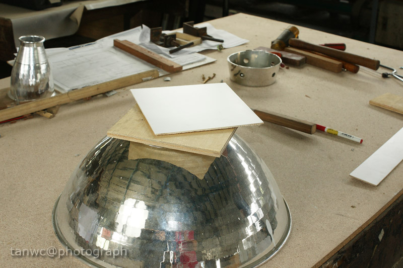
For the support plate, I glue two pieces of plywood, a 8mm thick plywood and a 3 mm ply with white laminate, together. The white laminate finished could as as a good reflection surface when it mounts into the bowl.

After the support plate being prepared, trace the diameter of the opening onto the plate. Cut out the round plate with table saw.

This plate will act as the main support plate for the inner reflector of the dish. The next step is to cut out an opening on this circular plate. The size of the opening should big enough to let the flash head go through it.

As shown in the pic above, the size of the my flash head, which is a F58am, is marked onto the plate. The three crosses would be the holes for the 4 inches length screws which will act as the middle reflector holding screws.

Cut the opening with a router and sand it out to get a smooth edges.
The next to do is the middle reflector.

I glue two pieces of 3mm ply with white laminates. I marked the centre of the plates which will be the centre point of the circular reflector, and the 3 screws holes as well. These holes were traced from the main support plate which were done earlier.
With proper tool, in my case, a table saw, cut out the reflector into a circular plate:

The three crosses are where the support screws will be. These three holes must be inline with the holes that been drilled on the base/support plate.
The diameter of the middle reflector is about 1cm bigger than the base plate.
Next, for the holding screws, I use the longest screws available that are easily purchase in the local hardware shop that I use to go.

The longest screws I could get is these 4 inches ones.

With nuts, the screws are fastened onto the base support plate....

And the middle reflector as well.

The view of the other side of suppor plate with flash head opening. The next photo shows where the support plate will be mounted to the reflector bowl.

Now, everything to be held in place by screws.


Complete Part 1. Next, would be the flash support bracket.
::Part 1 : The Design::
::Part 3 : The Flash Bracket::
1 comment:
Nice blogg thanks for posting
Post a Comment